Interrupts
Interrupts allow us respond to certain events by interrupting the current running code. This is a very useful thing in a microcontroller. This section will talk about interrupts in general but the concepts will apply to many of the built in peripherals like timers and the EUSART.
There are many different ways to trigger an interrupt on the PIC16F690. One of those is the External Interrupt pin. On the 16F690 this is pin 17 and it is called INT (RA2). This allows you to interrupt code execution when either a rising or falling edge is detected on the INT pin (RA2). One application of this would be a circuit that responds to a pushbutton. Instead of periodically checking the status of an input to see if a button was pressed, you can use the INT pin to interrupt the code when the button is pressed.
So what happens when an interrupt occurs? The answer is that the status of the system is saved (called the context), then the processor is pointed towards your interrupt code. The interrupt code runs and when it is done, the status (context) is restored and the processor is returned to where it left off. The regular code then proceeds as before.
The code that is run when an interrupt occurs is called an Interrupt Service Routine (ISR). It is a special function that only runs when there is an interrupt. The PIC16F690 can only have one Interrupt Service Routine. Other more advanced devices can have a separate routine for each type of interrupt.
If you are using interrupts, you must tell XC8 which function in your code is the interrupt handler. You do this when you declare the function by adding "interrupt" to the declaration:
void interrupt isr()
{
... interrupt code
}
This tells the compiler that isr() is the function that will get called when an interrupt occurs. Note that an interrupt service routine can not take any arguments and does not return anything. This makes sense because you do not call the ISR manually. It is called automatically when an interrupt occurs.
Interrupts can be enabled and disabled. Each interrupt has an interrupt enable bit in one of several registers. For example, the INT pin interrupt enable bit (INTE) is found in the INTCON register as shown below.
| INTCON |
| 7 | 6 | 5 | 4 | 3 | 2 | 1 | 0 |
| GIE | PEIE | T0IE | INTE | RABIE | T0IF | INTF | RABIF |
Also, before any interrupt can occur, the Global Interrupt Enable bit must be set. This is called GIE and is also found in INTCON. PEIE is the Peripheral Interrupt Enable bit and it must be set before a peripheral interrupt can occur. However, the INT pin interrupt is NOT a peripheral interrupt so this does not affect us right now.
The last thing we must decide for the external interrupt is if the interrupt will occur on the rising or falling edge of the input signal. This is controlled by the INTEDG bit of the OPTION_REG register. A 1 means interrupt on the rising edge, a 0 for falling edge.
| OPTION_REG |
| 7 | 6 | 5 | 4 | 3 | 2 | 1 | 0 |
| RABPU | INTEDG | T0CS | T0SE | PSA | PS2 | PS1 | PS0 |
Let's work from our example before. We will add a second LED to pin RC7. We also attach a pull-down resistor to INT (RA2). Finally, we will connect a switch between Vcc and the INT pin. If you don't have a switch, just use a piece of wire!
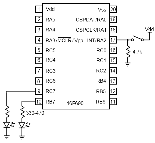 Circuit with 2 LEDs and switch.
In the code below we will use an interrupt to flip a digital output (LED2) every time a rising edge is detected on the INT pin. Meanwhile, LED1 will continue to blink as the main program loop runs. You can also directly download this code with comments here: interrupt_example.c
#include <xc.h>
#pragma config FOSC=INTRCIO, WDTE=OFF, PWRTE=OFF, MCLRE=ON, CP=OFF, \
CPD=OFF, BOREN=OFF, IESO=OFF, FCMEN=OFF
#define _XTAL_FREQ 4000000
#define LED1 PORTBbits.RB7 //Create meaningful names for our pins
#define LED1_TRIS TRISBbits.TRISB7
#define LED2 PORTCbits.RC7
#define LED2_TRIS TRISCbits.TRISC7
void interrupt isr()
{
//reset the interrupt flag
INTCONbits.INTF = 0;
LED2 = ~LED2; //flip the bit
//The ~ (tilde) is the complement operator
}
int main()
{
TRISA = 0xFF; //set all digital I/O to inputs
TRISB = 0xFF;
TRISC = 0xFF;
ANSEL = 0x00; //disable all analog ports
ANSELH = 0x00;
LED1_TRIS = 0; //LED1 is an output
LED2_TRIS = 0; //LED2 is an output
INTCONbits.INTF = 0; //reset the external interrupt flag
OPTION_REGbits.INTEDG = 1; //interrupt on the rising edge
INTCONbits.INTE = 1; //enable the external interrupt
INTCONbits.GIE = 1; //set the Global Interrupt Enable
///////////////////////
// Main Program Loop //
///////////////////////
while(1)
{
LED1 = 1; //Flash LED1
__delay_ms(500);
LED1 = 0;
__delay_ms(500);
}
return 0;
}
This first thing to do is to configure the external interrupt. Step one is to clear the interrupt flag for the external interrupt. This bit stores whether or not an interrupt has occurred. This bit can be set by the system regardless of whether or not the interrupt is enabled. That means you can manually poll the interrupt flag even if you do not want to use an interrupt service routine (isr). We initially clear the interrupt flag to clear any interrupts that may have come in before getting this far.
The next line sets the interrupt to trigger on the rising edge of the input signal to the INT pin. In this case, we want to interrupt when the switch is closed which will be a rising edge.
Next we enable the external interrupt and finally set the Global Interrupt Enable bit. Our device is ready to interrupt.
Above the main() routine I've declared the ISR. Since there is only one interrupt enabled on our system, the routine just assumes that an external interrupt has occured. If you enable more than one interrupt, you will have to check the interrupt flags to determine which triggered the interrupt. This can be accomplished simply with IF statements:
void interrupt isr()
{
if(INTCONbits.INTF == 1)
{
//reset the interrupt flag
INTCONbits.INTF = 0;
PORTCbits.RC7 = ~PORTCbits.RC7; //flip the bit
}
else if(...)
...
}
The ISR should always clear the interrupt flag that triggered the interrupt. If you do not do this, another interrupt will occur immediately after ISR completes. This will effectively halt the operation of the main function. In our case, if we did not clear INTCONbits.INTF, the interrupt would repeatedly occur even if the switch wasn't closed again. LED2 would turn on and off extremely quickly (several thousand times per second, depending on the oscillator frequency and the exact number of instructions in the ISR). LED1 would stop flashing entirely.
Once the interrupt flag has been cleared we can proceed to do whatever it is we want when the interrupt occurs. In this case, we are toggling LED2 as a visual indicator that the interrupt has indeed occurred.
Interrupt Service Routines should not take long to run. Typically you want to get in and out as fast as possible so that your main code can continue.
Before it was mentioned that ISRs have no arguments and return no values. If you need an ISR and the main routine to share information, you can declare a global variable so that both routines have access to it. However, if the ISR writes to that variable, your main routine must be written in such a way that it can handle sudden changes in that variable. This is necessary because an interrupt can occur at any time.
Let's look at an example of where this could get us into trouble. In the example code, the state of Port C is recorded each time an interrupt occurs and the value is stored as a command. In the main function, the commands coming in are checked to see if they are non-zero, and if they are, they are saved as current command.
unsigned int index = 0;
char commands[8];
void interrupt isr()
{
//reset the interrupt flag
INTCONbits.INTF = 0;
index++;
if(index>=8)
index = 0; //cycle to the beginning of the array
commands[index] = PORTC; //read 8-bit parallel data from PORT C
}
void main()
{
char currentCommand;
if(commands[index] != 0)
currentCommand = commands[index];
if(currentCommand == 1)
{
//handle command 1
}
else if(currentCommand == 2)
{
//handle command 2
}
... etc
}
Issues may arise in our if(commands[index] != 0) statement. Let's say that index is currently 0 and commands[0] = 1; So, when the processor reaches the if statement, the expression will be true and the if statement will run. If at this very instant, an interrupt occurs, the code will jump to the ISR. At this point, index will be incremented to 1. Let's say a command of '0' is read on Port C. When the ISR returns execution, we will be continue where we left off. At this point we read command[index] but index has now been incremented to 1.
 The variable "index" changes suddenly and causes issues.
Because of the sudden change in the variable "index", the command we check (command[0]) is not the command that is stored for later processing (command[1]).
There are two ways this issue can be handled. The easiest is to store commands[index] in currentCommand at the beginning and to refer to currentCommand throughout the code. This means that the commands[] array is accessed only once when handling a command thus preventing a mixup.
Another method to avoid sudden changes in "index" could be to disable the external interrupt while handling the command and re-enabling the interrupt when you are done.
When you start using interrupts, you must always keep in mind that interrupts can occur at any time during execution.
In the next section we will start using timers to create time based events.